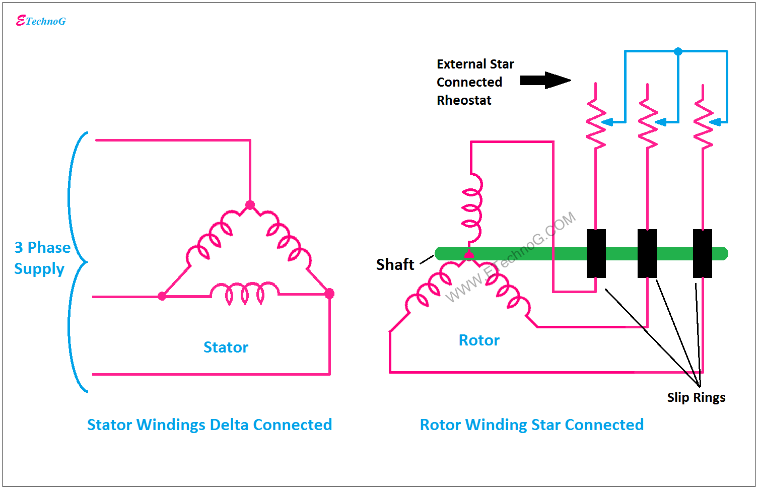
Slip Ring Motor Starter Circuit Diagram
Motor synchronous starting slip ring methods induction method resistance motors rotor principle working damper speed electrical self torque cage squirrel Starter motor slip ring induction used type delta star contactor circuit Motor ring starter slip diagram schematic magna generation start system speed
Concepts Of Slip Rings And Brush Assembly In Three Phase Induction
Magna start – new generation slip-ring motor starter Concepts of slip rings and brush assembly in three phase induction Why the rotor of slip ring induction motor always star connected
Slip rings three motor induction rotor wound phase ring brush circuit concepts assembly rotating machine electrical fig engineering stationary connecting
Slip ring starter motor resistance induction liquid magna generation start electrical motors3 phase motor control circuit diagram forward reverse pdf 6.6kv slip ring induction motor liquid starterWhat are the type of starter used for slip ring induction motor?.
Magna start – new generation slip-ring motor starterSlip ring motor rotor wound diagram induction resistance phase connection schematic rings motors brushes external torque everything ever need know Electrical schematic – motor starting system – slip ring motor startingPhase circuit rotor wiring kontrol reverse forward.

Self start 3-φ induction motor slip-ring wound rotor starter
6kv induction existingSchematic expert slipring cannot started Slip ringElectrical standards: slip ring induction motors starting; slip ring.
Motor rotor circuit wound power electrical diagram control schematic induction bank wiring automatic hoist ac resistors guide used step electronicsEverything you’ll ever need to know about slip ring motors Slip motor induction ring star connected rotor delta diagram connection why which very will always explained reasons problem simple thereGuide to the power circuit and control circuit of the wound rotor ac.
Synchronous motor starting methods
Medium voltage soft starter for heavy-duty motor controlSlip ring starter phase rotor power three control diagram diagrams .
.


