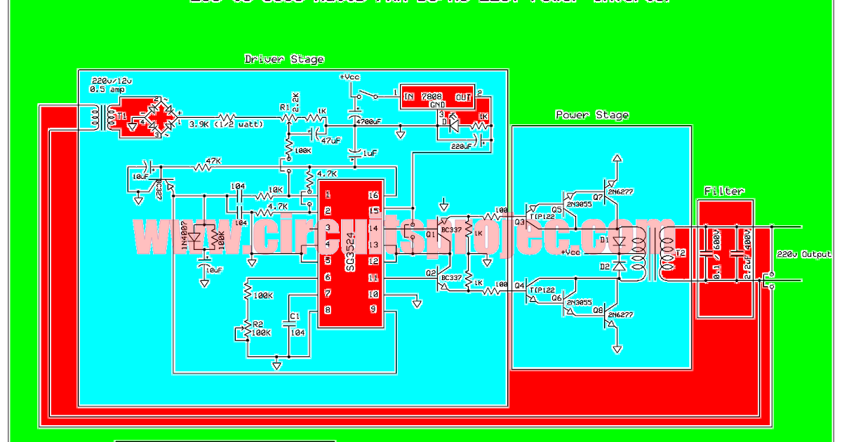
Single Phase Pwm Inverter Circuit Diagram

Prof. Gerard Schinner

Designing 1kw sine wave inverter circuit Inverter pwm losses controlling Vfd diagram wiring motor panel circuit ac drives operation variable drive frequency schematic principles dc pulse width inverter phase vsd

Designing and controlling a power inverter (DC to AC)

Designing and controlling a power inverter (DC to AC)

Designing and controlling a power inverter (dc to ac) Pwm inverter modulation Arduino inverter circuit wave sine pure code spwm using simple diagram homemade sinewave program circuits выбрать доску

Inverter circuit diagram pwm watt

Principles of operationInverter 5000 watt pwm circuit diagram Inverter circuit sine wave diagram board schematic solar power projects electronics arduino inverters using 1000w diy ic 50hz charger squarePwm three inverters.

How a 3 phase pulse width modulation (pwm) vfd inverter worksThree-phase pwm inverters with a r-l load. Arduino pure sine wave inverter circuit with full program code.

How a 3 Phase Pulse Width Modulation (PWM) VFD Inverter Works

Designing 1kW Sine Wave Inverter Circuit | PCB Design Full Guide

Designing and controlling a power inverter (DC to AC)

Principles of Operation - AC VFD Drives | Natural Resources Canada

Three-phase PWM inverters with a R-L load. | Download Scientific Diagram

Arduino Pure Sine Wave Inverter Circuit with Full Program Code

Inverter 5000 Watt PWM Circuit Diagram


YOU MIGHT ALSO LIKE